Being a safety system, CROME has to be compliant with both radiation monitoring standards and with Safety Integrity Level 2 according to the IEC 61508 standard. To reach the objective, the safety function must meet all requirement in term of :
- Systematic Safety Integrity : It is basically a quality assurance process that should be scaled according to the SIL level in order to minimize design, installation , operation and maintenance errors. It is actually a qualitative approach.
- Hardware Safety integrity which is related to random hardware failures
- Software Safety integrity relates to the safety integrity achieved by having adapted restrictions for application programming methods, tools and associated procedures
Systematic Safety Integrity (Quality assurance)
A complete presentation can be found in this link : https://indico.cern.ch/event/1030567/contributions/4327277/attachments/2243321/3804038/CROME_PMMU_Hamza_Boukabache.pdf
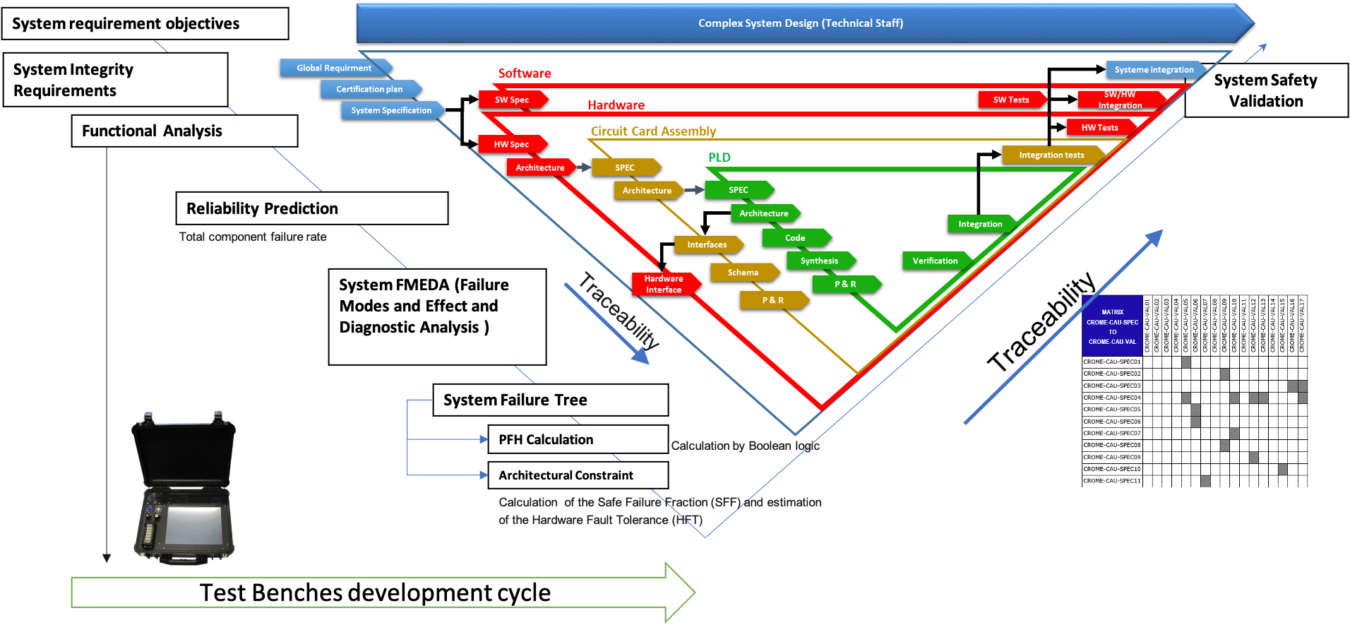
The design process is divided into multiple V cycles that combines the development process of the HW/SW and a safety assurance process.
Hardware Safety Integrity Assessment
Given the high expectations regarding the reliability of the monitoring system, its development process was supported by an extensive dependability study according to the IEC 61508 standard and its production has been almost entirely carried out at CERN, thanks to intra-departmental collaboration with TE, BE, EN and EP.
For the hardware integrity and functional verification of both the hardware and firmware, we have followed methodologies in accordance with the Safety Integrity Level (SIL) 2 as required by the IEC60532 [1].
Hardware safety integrity is related to random hardware failures and comprises quantitative and qualitative requirements. Quantitative requirements include the calculation of the Probability of a Failure on Demand (PFD) or the Probability of a dangerous Failure per Hour (PFH) of the safety system. Qualitative requirements are related to the architectural constraints that limit the achievable Safety Integrity Level (SIL) based on Hardware Fault Tolerance (HFT) and the Safe Failure Fraction (SFF) of the sub-systems.
The verification methodology we followed for the CROME system comprises the following main steps:
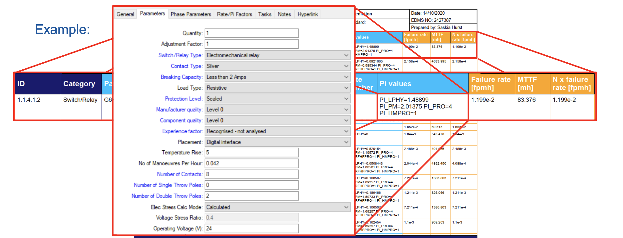
Reliability Prediction: The first step of this approach is a reliability prediction for all components of the system. The failure rate of each component is estimated as Mean Time To Failure (MTTF) or Failures In Time (FIT) by either using standards (FIDES), field data or values from the manufacturer calculated through accelerated lifetime tests. These failure rates are the basis for all further calculations.
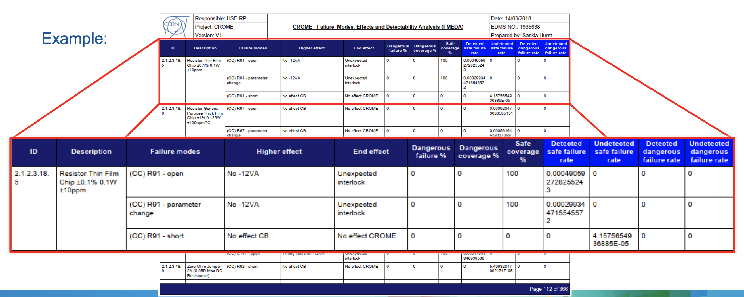
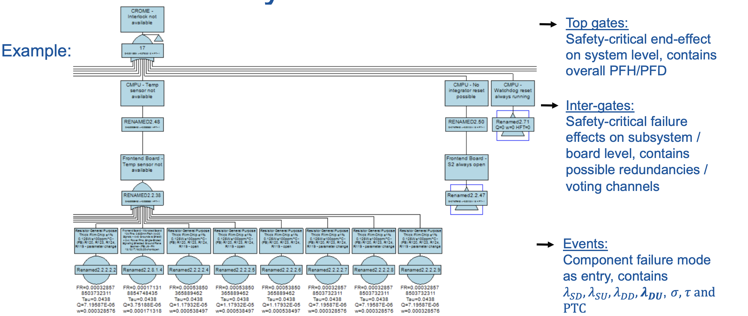
Failure Modes, Effects and Diagnostic Analysis (FMEDA): The second step is a Failure Modes, Effects and Diagnostic Analysis (FMEDA) where the necessary parameters λSD, λSU, λDD and λDU (safe detectable, safe undetectable, dangerous detectable and dangerous undetectable failure rate respectively), which are needed for the calculation of PFH and SFF, are determined. The FMEDA analysis was performed together with the board designers. Compared to standard FMEA, where all failure modes of each component, their immediate failure effects, failure effects at system level and failure causes are determined, a FMEDA does also include the failure mode probabilities and their diagnostic coverage. The failure rates come from the prediction and the failure mode probabilities can be obtained from standards or other databases. From the results of the FMEDA, the architectural constraints can be directly determined.
Fault Tree Analysis: The PFD or PFH can be calculated by using Fault Tree Analysis (FTA) based on the calculated failure rates λSD, λSU, λDD and λDU in the FMEDA. The calculation only takes the dangerous undetectable failures into account.
The results of the PFH and architectural constraints are then compared against the requirement tables of the standard and the achievable SIL can be determined. Considering both a PFH of 9.28 10-8 failures per millions of hours and a safe failure fraction of 97.4%, the hardware safety integrity of the CROME system conforms to SIL 2.
All the methodology has been published and can be found here : https://www.rpsonline.com.sg/proceedings/esrel2020/pdf/5287.pdf
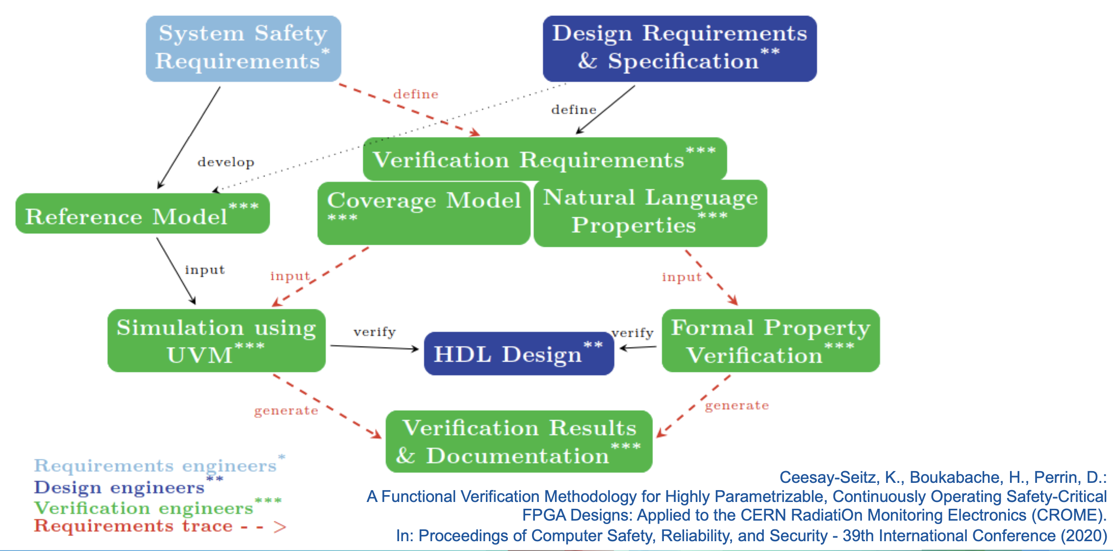
Functional Verification Methodology
In order to be able to rely on the autonomous decisions regarding safety critical outputs, the functionality of the design must be systematically verified against its requirements. We perform functional verification according to our verification methodology in accordance with the IEC 61508 standard for safety-related programmable electronics.
As defined in IEC 61508, the Standard for Functional Safety of Electrical/Electronic/Programmable Electronic Safety-Related Systems, the safety life cycle follows the V-Model. A customized V-Model for the CROME project can be seen in Figure 1.
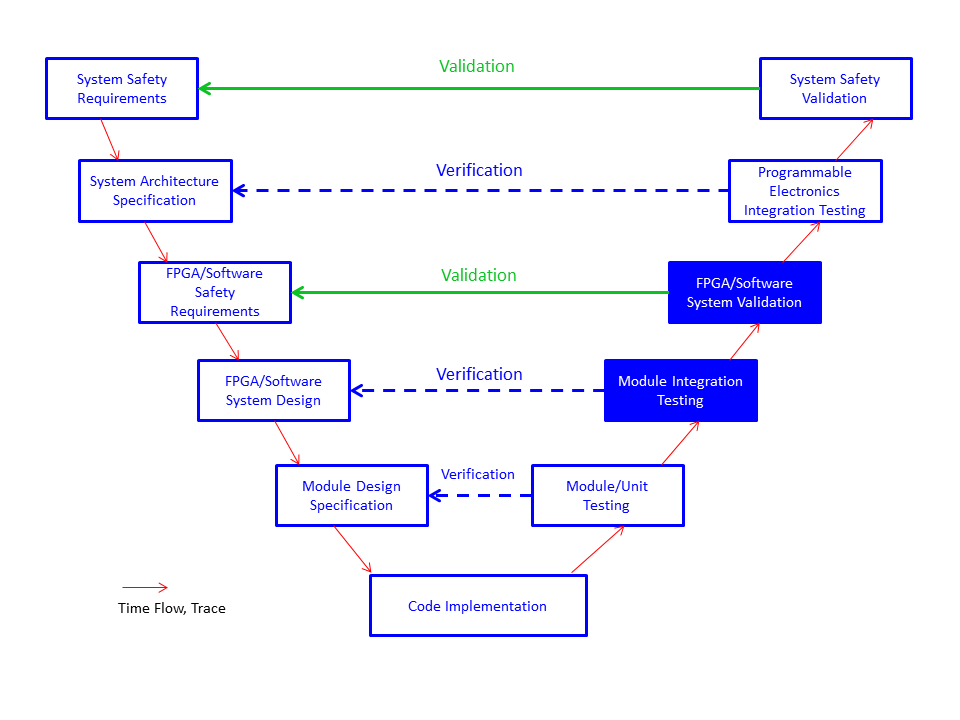
The highlighted steps belong to System-on-Chip verification and validation. They are described in the flow bellow :
Functional Verification of FPGAs
Verification is the process of determining whether a system conforms to its specification. Typically 50% of an FPGA development project is spent in verification. With the increasing complexity of FPGA designs, this number has risen in recent years.
A common metric to measure verification progress is the tracking of functional coverage. Functional coverage measures how many of a design's functions have been verified. These functions are described in the requirements. For safety-critical systems it not only has to be shown that the system fulfils all of its requirements, but it also needs to be shown that the system does not behave in any other way than specified. Therefore, the verification requirements need to contain additional statements that describe the absence of unintended functionalities.
Functional verification of Hardware Description Language (HDL) designs can be divided into simulation-based verification and formal verification. Simulation based verification can only provide evidence that the design behaves as intended for the specific simulation scenarios that have been tested, that is for the specific input stimuli applied at specific design conditions. Simulating all possible input scenarios with currently available computers and tools would take many years. In the contrast formal verification can mathematically prove that a design always behaves as specified for any kind of inputs. Unfortunately formal verification on full system level would often require more human and computing resources than available. The solution is to combine both techniques and benefit from each’s advantages.
Constrained-Random Simulation with Functional Coverage and the Universal Verification Methodology (UVM)
Simulation-based verification is done by simulating the FPGA in a simulation tool. The tool simulates the behaviour of the HDL code that will be later programmed into the FPGA. A verification engineer can specify input signals that are sent to the Design Under Verification (DUV), i.e. the simulated HDL design. The simulator computes the results which can then be verified by the verification engineer. In early years these activities have been done manually. Today it is possible to write complex automated testbenches that automatically generate constrained random input signals and verify the computed results. The expected results can be generated by a reference model. The reference model for the verification of the CMPU has been written independently from its HDL counterpart. An important concept of safety-critical electronics development has been applied: independence between the design and the verification engineers.
The testbench for the CMPU has been written in SystemVerilog. This language combines features of high-level languages with those of HDLs. It allows object oriented programming, the usage of operating system libraries and can interface with libraries written in other languages, e.g. in C or Python. Additionally to these high-level concepts, it supports parallelized blocks that are automatically executed as separate simulation threads, blocking and non-blocking assignments, 4-state logic and many more hardware concepts.
Constrained random simulation means that input signals to the DUV are generated randomly. The randomization code is guided by constraints that are dynamically applied during a test run. Rather than specifying hundreds of test cases manually, a verification engineer designs test runs with different constraints. This allows the automatic generation of thousands of test cases, far more than one would ever simulate with manually specified inputs. The advantage is furthermore that the range of tested values can be customized. It can be evenly distributed over the whole possible input range or certain ranges can be given higher priorities in order to test corner cases.
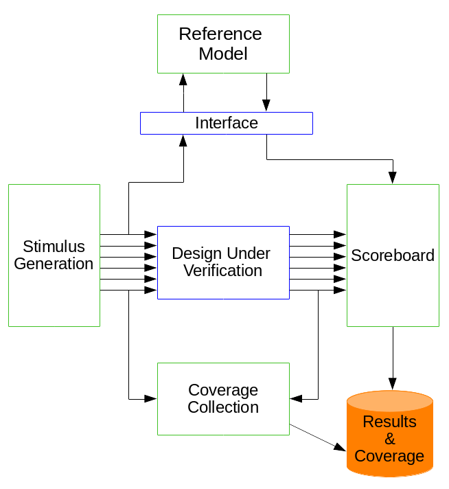
The Universal Verification Methodology (UVM) is a verification methodology that builds on best practices in simulation-based electronic design verification. It combines the benefits of all its predecessors. It defines concepts for implementing testbenches in a reusable way. Reusability is facilitated through a simulator- and therefore vendor-independent open-source SystemVerilog library.
UVM uses many advantages of SystemVerilog, especially its object oriented programming capabilities and preprocessor macros. For functional coverage collection it completely relies on SystemVerilog. A SystemVerilog class becomes a UVM component by being derived from a UVM base class. The factory pattern is used to increase flexibility and reusability by allowing object type overriding after compile time. Type overriding can also happen at runtime, depending on a testbench internal configuration or condition or enforced from the command line. This allows e.g. to reuse the same test case and testbench components for sending several different input sequences to the DUV.
UVM divides a test run into several phases. Testbench components that are registered with the UVM factory can implement code for these phases. At runtime the phases are traversed in a defined order. Each of them has its specific task like configuring the verification environment, applying stimuli or generating reports.
UVM uses Transaction Level Modelling (TLM). Test scenarios can be specified or randomly generated in sequences that can be scheduled in fixed or random orders. The sequences send transactions to the UVM driver, which sends the actual input signals to the DUV. After the simulator has computed the results, a UVM output monitor reads the output signals and combines them to an output transaction. The input and corresponding output transactions are sent to the UVM scoreboard for verifying the results. This scoreboard can interface with a reference model, which can be written in another language, e.g. in C. Input and output transactions can also be passed to a functional coverage collector.
Formal Property Verification
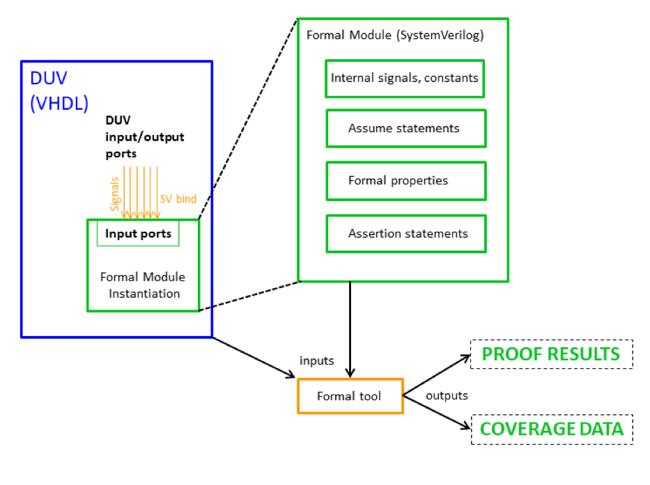
Formal verification mathematically proves that a design satisfies its specification for all possible input value sequences. It has been used in hardware verification for many years. In most projects it is only used for critical subparts of a design, mostly for strictly defined control logic and protocols. Computing resources and tool capabilities often don’t suffice to use it on full system. Many different formal verification techniques for hardware and software exist. One of them is Formal Property Verification (FPV).
FPV tools typically implement bounded model checkers to prove properties written in hardware verification languages. Properties might be proven for all possible states, it might be shown by a counterexample that they can be violated or they might be inconclusive. Inconclusive properties can be proven from the initial state up to a certain number of clock cycles, which is then the proof bound. If it can be shown that a design is able to calculate all outputs within this number of clock cycles, the design can be considered as verified. Several commercial tools for formal property verification exist, which are qualified according to the IEC 61508 standard for functional safety. They can directly take HDL code as input. The temporal propositions for these tools can be specified in several languages, e.g. in the Property Specification Language (PSL) or as SystemVerilog Assertions (SVA). These languages extend Linear Temporal Logic (LTL) formulas by sequential extended regular expressions. They can be used to describe repeating scenarios. Like mentioned, formal verification is typically not done on a complete system. Mostly it is accompanied by simulation or emulation. An advantage of using these languages is that they can be directly used in simulation as well, which can serve as a verification of the properties themselves.
Coverage of formal properties can be measured as well. It can be combined with the coverage results of simulation.
[1] Saskia Kristina Hurst, Hamza Boukabache, Daniel Perrin, Overview of a Complete Hardware Safety Integrity Verification According to IEC 61508 for the CERN Next Generation of Radiation Monitoring Safety System, Proceedings of the 30th European Safety and Reliability Conference and the 15th Probabilistic Safety Assessment and Management Conference
[2] Accellera System Initiative: Universal Verification Methodology (UVM), Napa, CA 94558, United States of America, 2014
[3] Katharina Ceesay-Seitz: Automated Verification of a System-on-Chip for Radiation Protection fulfilling Safety Integrity Level 2 (SIL 2), Diploma Thesis, TU Wien, Vienna, Austria, February 2019